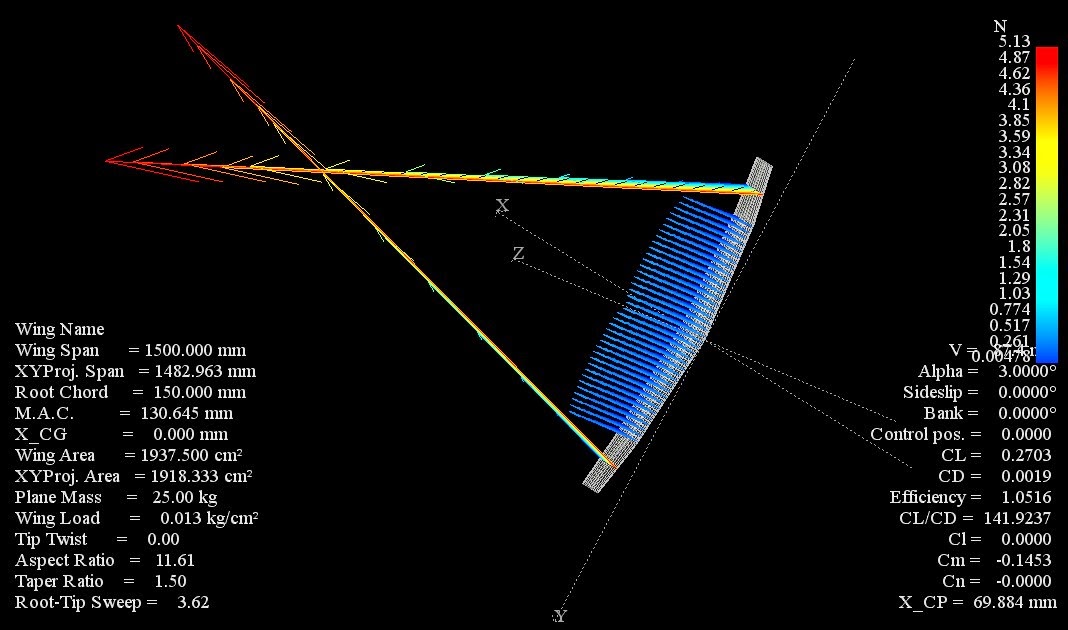
Many custom inputs for styling the graph are presented in the screenshot below.0. Below are some screenshots of the tests with the two different airfoils. I cannot get the graph to display a nice CL vs AoA curve, but only a single value.
#Xflr5 half wing how to#
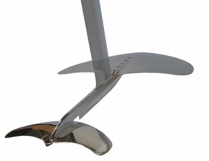
I am not sure how to select the right airfoil for my wing now.įor these tests, i used the XFLR5 software. Drela 2 to analyze one-element airfoils, but its abilities have been. This result confused me since I expected the wing with the FX76MP120 airfoil to have a better L/D ratio. XFLR5 software, an implementation of widely recognized XFOIL created by M. I have added screenshots of the results of the XFLR5. It seems that the twist in XLFR5 works only around the Y axis. 5.10 Symmetry A symmetric calculation reduces the matrixs size by approximately half (exception is the fin). Then I simulated the exact same wing with the NACA4412 airfoil (which has a lower L/D ratio than the FX76MP120) and this wing surprisingly had a L/D ratio of 31. it seems to me impossible to design a winglet with a twist angle changing from root to tip. However, when I simulate this wing in XFLR5 I get a L/D ratio of 26 which is quite a low value. Therefore I designed the wing with the FX76MP120 airfoil. In other words, if you had to decide to spend 10 min-utes of your time between shaping an exact airfoil, or trim-ming the final glider for flight, you should always spend the The home of model gliding us debt clock Airfoil Glider For our annual homeschool science fair, he expressed interest in designing different airfoils (cross sectional shape of a wing) for a. The airfoil that had the best L/D ratio was the FX76MP120 for Reynolds numbers around 500 000. For the first effect, you can try to insert a fuselage between the two half wings, and to leave a gap between the fuselage and the inner wing section. The two main effects of the fuselage are the disturbance of the potential flow around the wings, and its viscous drag. The root cord is 12.7cm and I am designing it to foil at 5m/s.įor the airfoil initially, I was using the airfoil with the highest L/D at my Reynolds number (which goes from 280 000 to 650 000, since the chord of the wing changes along the wingspan). This was one of the motivations behind the development of flow5. I have also designed it to have an elliptical lift distribution to minimize induced drag. The requirements for the main wing is for it to have a wingspan of 1m and an area of 0.1m^2. Up to this point, I have only been designing the main wing. If you're using a VLM what you're measuring is the CDi of a wing geometry, which is going to be most strongly dependent on CL.I have been designing a hydrofoil lately and have tried to optimize it for the lift over drag ratio.

The second wing is generating less drag, but also less lift at a given angle of attack the comparison isn't really fair.

It would be clearer to look at a polar of CL plotted against CD the best point of comparison is to look at the drag generated at the same CL, not the same angle of attack (because the zero-lift angle of attack will change with wing design as well). Is the airfoil t/c constant across both wings? That will also have an effect. The way to think about this is that the CD of a wing is going to be strongly dependent on the aspect ratio $AR$, the taper ratio $\lambda_T$, the chord and twist distribution along the wing, as well as the airfoil distribution. The aspect ratio of the first wing is higher than the second wing, so you're varying more parameters than just the tip chord.

If one defines an analysis for a Type-II polar and then runs it, one gets a Type-II polar. Suppose one launches XFLR5 and goes to Direct Analysis. It is a bug everyone using XFLR5 should be on the lookout for. It may be inaccuracies in your modeling method it's hard to say without more info.įirst, this isn't quite an apples-to-apples comparison. I've wasted a few days of analysis - again - bacause of a bug in XFLR5.


 0 kommentar(er)
